こんばんは!
今回はArduinoとProcessingでGUIを使用してのLED制御をやっていきます。
使用するもの
・Arduinoメインボード(https://amzn.to/2vkPIUH)
・USBケーブル(https://amzn.to/2UHhntl)
・ブレッドボード(https://amzn.to/38eNi8u)
・ジャンパワイヤ (https://amzn.to/39uBU8T)
・LED×3(青赤黄)(https://amzn.to/2sN4LSe)
・100Ω抵抗(https://amzn.to/2FRFG1o)
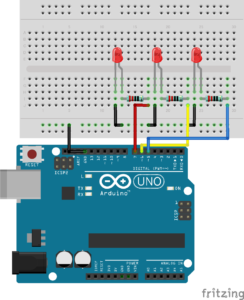
配線
まず配線からやっていきます。
以下の図のように配線します。
Arduino側のプログラム
次にArduino IDEを起動して次のコードを記述します。
1 2 3 4 5 6 7 8 9 10 11 12 13 14 15 16 17 18 19 20 21 22 23 24 25 26 27 28 29 30 31 32 33 34 | const int red = 5; const int yellow = 6; const int blue = 7; void setup() { Serial.begin(9600); //start serial communication @9600 bps pinMode(red, OUTPUT); //set pin as output , blue led pinMode(yellow, OUTPUT); //set pin as output , red led pinMode(blue, OUTPUT); //set pin as output , yellow led } void loop() { if (Serial.available() > 0) { char data = Serial.read(); if (data == 'r') { digitalWrite(red, HIGH); } if (data == 'y') { digitalWrite(yellow, HIGH); } if (data == 'b') { digitalWrite(blue, HIGH); } if (data == 'a') { digitalWrite(red, HIGH); digitalWrite(yellow, HIGH); digitalWrite(blue, HIGH); } if (data == 'd') { digitalWrite(red, LOW); digitalWrite(yellow, LOW); digitalWrite(blue, LOW); } } } |
Processingとシリアル通信をし、「r」を受信すると赤のLEDを点灯、「y」を受信すると黄のLEDを点灯、「b」を受信すると青のLEDを点灯、「a」を受信すると3つ全てのLEDを点灯、「d」を受信すると3つ全てのLEDを消灯します。
コードを記述したらメインボードに書き込みます。
Processing側のプログラム
次にProcessingを起動して次のコードを記述します。
1 2 3 4 5 6 7 8 9 10 11 12 13 14 15 16 17 18 19 20 21 22 23 24 25 26 27 28 29 30 31 32 33 34 35 36 37 38 39 40 41 42 43 44 45 46 47 48 49 50 51 52 53 54 55 56 57 58 59 60 61 62 63 64 65 66 67 68 69 70 71 72 73 74 75 76 77 78 79 | import controlP5.*; import processing.serial.*; Serial port; ControlP5 Button; void setup() { size(300, 150); Button = new ControlP5(this); port = new Serial(this, "COM5", 9600); Button.addButton("red") .setPosition(10, 20) .setSize(50, 50) .setColorActive(color(0, 40)) .setColorBackground(color(255, 0, 0)) .setColorForeground(color(255, 0, 0)) .setColorCaptionLabel(color(0)); Button.addButton("yellow") .setPosition(width/2-25, 20) .setSize(50, 50) .setColorActive(color(0, 40)) .setColorBackground(color(255, 255, 0)) .setColorForeground(color(255, 255, 0)) .setColorCaptionLabel(color(0)); Button.addButton("blue") .setPosition(240, 20) .setSize(50, 50) .setColorActive(color(0, 40)) .setColorBackground(color(0, 0, 255)) .setColorForeground(color(0, 0, 255)) .setColorCaptionLabel(color(0)) ; Button.addButton("alloff") .setPosition(2*width/3-25, 90) .setSize(50, 50) .setColorActive(color(0, 40)) .setColorBackground(color(40)) .setColorForeground(color(40)) .setColorCaptionLabel(color(255)) ; Button.addButton("allon") .setPosition(width/3-25, 90) .setSize(50, 50) .setColorActive(color(0, 40)) .setColorBackground(color(200)) .setColorForeground(color(200)) .setColorCaptionLabel(color(0)) ; } void draw() { background(150); } void red() { port.write('r'); } void yellow() { port.write('y'); } void blue() { port.write('b'); } void alloff() { port.write('d'); } void allon() { port.write('a'); } |
Arduinoとシリアル通信をし、REDボタンを押すと「r」を送信、YELLOWボタンを押すと「y」を送信、BLUEボタンを押すと「b」を送信、ALL ONボタンを押すと「a」を送信、ALL OFFボタンを押すと「d」を送信する処理が記述されています。
ポート番号とポートの通信速度はArduino側と同じに変更してください。
ボタンの作り方、controlP5ライブラリの使い方はこちらの記事をご覧ください。
実行
コードの記述が終わったら左上の実行ボタンを押してください。
実行画面のボタンを押してLEDが点灯するか確認してみてください。
全てが上手くいっていれば以下の動画のようになるはずです。
参考
今回のシステムを作るのにこちらのサイトを参考にさせていただきました。
https://www.hackster.io/hardikrathod/control-arduino-using-gui-arduino-processing-2c9c6c
まとめ
今回はProcessingとArduinoを使ってPCからLEDを制御できるようなものを作ってみました。
GUIを使って様々なことができそうなので今後試していきたいと思います。
今回はこれで終わります。
ではまた!