こんばんは!
今回はスマートフォンとArduinoを使ってRGB LEDの色を無線でコントロールしてみます。
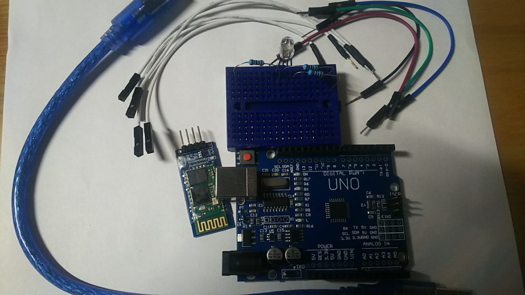
使用するもの
・Arduinoメインボード(https://amzn.to/2vkPIUH)
・USBケーブル(https://amzn.to/2UHhntl)
・ブレッドボード(https://amzn.to/38eNi8u)
・ジャンパワイヤ (https://amzn.to/39uBU8T)
・100Ω抵抗(https://amzn.to/2CiTT30)
・bluetoothモジュールhc-06(https://amzn.to/3cp7yGD)
・スマートフォンまたはタブレット
ダウンロードするアプリ
今回はColor LED Controllerというアプリを使ってBluetooth接続をします。
アプリはこちらからダウンロードできます。
Google Play : https://play.google.com/store/apps/details?id=appinventor.ai_yuanryan_chen.BT_LED
手順
まずハード側からやっていきます。以下の図のように配線してください。
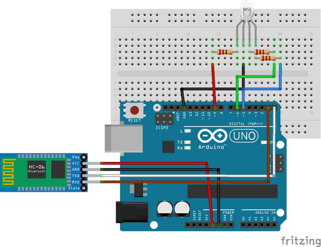
次にArduino IDEを起動して次のコードを記述してください。
1 2 3 4 5 6 7 8 9 10 11 12 13 14 15 16 17 18 19 20 21 22 23 24 25 26 27 28 29 30 31 32 33 34 35 36 37 | const int redPin = 9; const int greenPin = 6; const int bluePin = 5; void setColor(int red, int green, int blue) { analogWrite(redPin, red); analogWrite(greenPin, green); analogWrite(bluePin, blue); } void setup() { Serial.begin(9600); pinMode(redPin, OUTPUT); pinMode(greenPin, OUTPUT); pinMode(bluePin, OUTPUT); } void loop() { if (Serial.available() > 0) { int redVal = Serial.parseInt(); int greenVal = Serial.parseInt(); int blueVal = Serial.parseInt(); redVal = constrain(redVal, 0, 255); greenVal = constrain(greenVal, 0, 255); blueVal = constrain(blueVal, 0, 255); setColor(redVal, greenVal, blueVal); } } |
今回のコードの大部分は以前の記事に説明が書いてあるので、以前の記事に書いてない部分だけ説明します。
loop()関数内の
int redVal = Serial.parseInt();
というのは
シリアルバッファから整数値を読み取って、redValという変数に代入しています。
そして
redVal = constrain(redVal, 0, 255);
によって読み取った整数値を0~255の値に変換しています。
0~255である理由はanalogWrite(pin,val)関数のデューティー比(val)の値が0~255までであるからです。
これをマイコンボードに書き込んでみると以下の動画のようになるはずです。
ちなみにマイコンボードに書き込む際にはTX(D1)ピンとRX(D0)ピンにはジャンパワイヤを接続しないでください。書き終えたら接続するようにしてください。
理由などはこちらの記事に書いてあるので参考にしてください。
実際にスマートフォンとArduinoをBluetooth接続して実行してみた結果は以下の動画のようになるはずです。
まとめ
今回はBluetooth接続によって無線でLEDの色を変えることができました。
プログラムが少し複雑ですが、過去記事も参照してもらえば理解することができると思います。
今回はこれで終わります。
ではまた!